

 LED
LED

 LCD
LCD




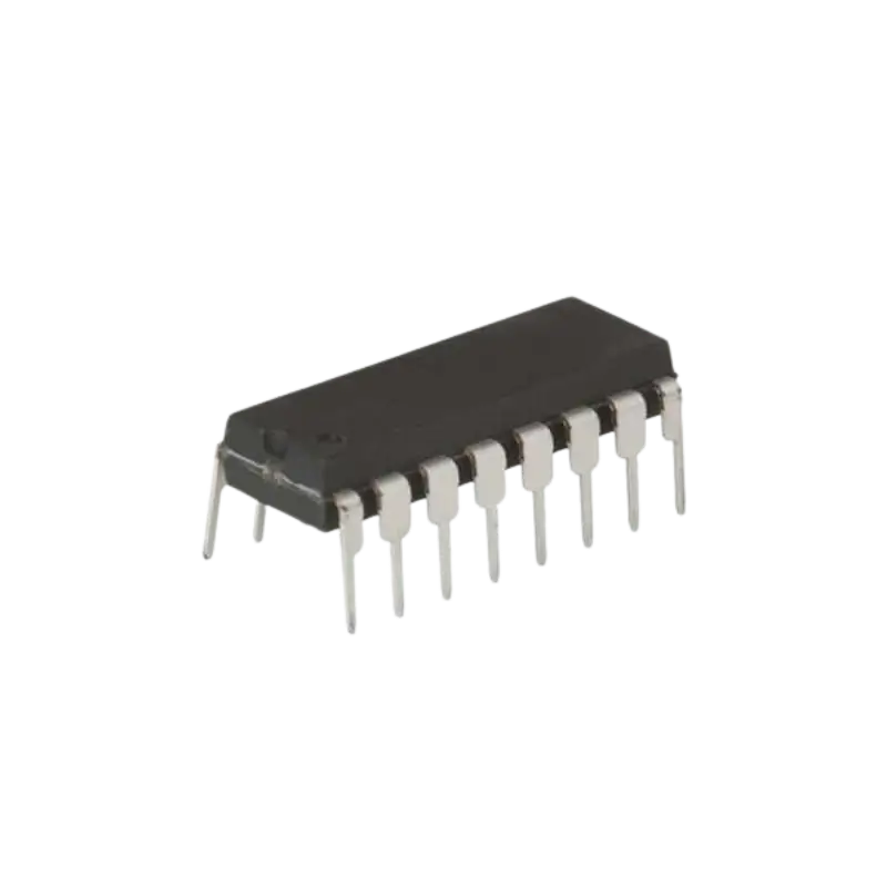


Product Description
The 4017 Decade Counter Divider IC is one of the most popular and versatile digital logic integrated circuits designed for sequential pulse counting, LED chaser effects, frequency division, and multi-stage timing applications. Operating as a 5-stage Johnson decade counter, it decodes clock pulses applied to its input and sequentially drives 10 individual outputs (Q0 through Q9) HIGH, one at a time, in a clean, non-overlapping sequence.
Engineered with a wide operating voltage range from 3V to 18V DC and extremely low static power consumption, the 4017 features fully buffered outputs capable of driving small LEDs or triggering transistor drivers directly. It includes a dedicated Carry Out pin (CO) that emits a complete square wave every 10 clock pulses, enabling seamless cascading for multi-digit counters. Housed in a standard 16-pin DIP package, it interfaces effortlessly with 555 timers, microcontrollers like Arduino, STM32, and ESP32, or discrete oscillator circuits. It is an ideal component for building LED chasers, electronic dice, sequencers, frequency dividers, and digital logic training kits.
⚠️ Reset & Enable Pin Setup Tip: For normal continuous counting, connect the Reset pin (Pin 15) and Clock Enable pin (Pin 13) to Ground (GND / Logic LOW). Bringing the Reset pin HIGH instantly resets the count back to output Q0. Bringing Clock Enable HIGH freezes the current count state and ignores incoming clock pulses.
Technical & Logic Architecture
This 10-output decade counter provides flexible sequential decoding:
Sequential 10-Stage Output: Decodes 10 individual active-HIGH outputs (Q0 to Q9) in linear sequence.
Cascading Carry Out Signal: Pin 12 (Carry Out) remains HIGH for counts 0 through 4 and LOW for counts 5 through 9, completing one cycle every 10 pulses to trigger secondary counters.
Wide Supply Voltage Range: Flexible operating supply voltage from 3V to 18V DC, enabling direct logic interfacing across 3.3V, 5V, 12V, and 15V systems.
Breadboard-Friendly Package: Standard 16-pin Dual In-Line Package (DIP-16) for easy insertion into breadboards and IC sockets.
4017 Truth Table (Function Table)
| Inputs: Reset (Pin 15) | Inputs: Clock Enable (Pin 13) | Inputs: Clock (Pin 14) | Active Output State | Operating Mode / Function |
| H | X | X | Q0 = HIGH (Q1-Q9 = LOW) | Asynchronous Reset (Forces output back to Q0) |
| L | H | X | No Change | Count Inhibit / Freeze (Ignores Clock) |
| L | L | Falling Edge | No Change | Clock Inhibit on Falling Edge |
| L | L | Rising Edge | Advances to Next Output (Q0 -> Q1 -> Q2…) | Increments Count Sequence on Clock Pulse |
Key Terms for Truth Table:
H: High Voltage Level (Logic 1 / VDD)
L: Low Voltage Level (Logic 0 / VSS)
X: Don’t Care (Can be High or Low)
Rising Edge: Low-to-High transition of the Clock signal
4017 Pinout Description & Logic Functions
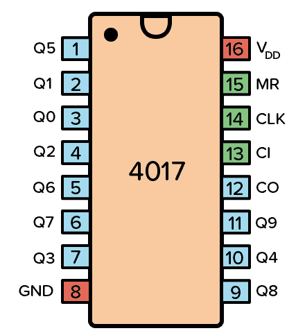
Pin 1 – Q5 (Output 5): Goes HIGH on the 6th clock pulse.
Pin 2 – Q1 (Output 1): Goes HIGH on the 2nd clock pulse.
Pin 3 – Q0 (Output 0): Active HIGH initial state (at power-on or after Reset).
Pin 4 – Q2 (Output 2): Goes HIGH on the 3rd clock pulse.
Pin 5 – Q6 (Output 6): Goes HIGH on the 7th clock pulse.
Pin 6 – Q7 (Output 7): Goes HIGH on the 8th clock pulse.
Pin 7 – Q3 (Output 3): Goes HIGH on the 4th clock pulse.
Pin 8 – VSS (GND): Ground reference pin (0V).
Pin 9 – Q8 (Output 8): Goes HIGH on the 9th clock pulse.
Pin 10 – Q4 (Output 4): Goes HIGH on the 5th clock pulse.
Pin 11 – Q9 (Output 9): Goes HIGH on the 10th clock pulse.
Pin 12 – CO (Carry Out): Emits 1 pulse for every 10 input clock pulses (for cascading additional 4017 ICs).
Pin 13 – CE (Clock Enable / Inhibit): Active-LOW enable line. Connect to GND for continuous counting.
Pin 14 – CLK (Clock Input): Triggers count sequence on Low-to-High (Rising Edge) clock transition.
Pin 15 – RST (Reset): Asynchronous Master Reset (Active HIGH). Drive HIGH to force output back to Q0.
Pin 16 – VDD: Positive power supply input pin (+3V to +18V DC).
Operating Modes Summary
Decade Sequential Counting: Automatically steps through Q0 to Q9 sequentially on each clock pulse and wraps back to Q0 on the 11th pulse.
Custom Sequence Truncation (Short Counting): Connect any desired output (e.g., Q6) directly to the Reset pin (Pin 15) to create custom modulus counters (e.g., a 6-step sequencer counting Q0 through Q5).
Multi-Stage Cascading: Connect Pin 12 (CO) to the Clock input of a second 4017 IC to build 100-step counters and decade dividers.
Applications
LED Chasers & Running Lights: Driving sequential LED displays for decorative lighting and visual displays.
Electronic Dice & Sequencers: Creating random generators and step sequencers for audio synthesizer projects.
Frequency Division & Timing: Dividing clock signal frequencies by factors from 2 to 10 for industrial control timing.
Technical Specifications
| Parameter | Value / Specification |
| Logic IC Family | CD4000 Series |
| Supply Voltage (VDD) | 3.0V to 18.0V DC |
| Logic Function | 5-Stage Johnson Decade Counter / Divider |
| Decoded Outputs | 10 (Q0 through Q9) |
| Package Type | DIP-16 (16-Pin Through-Hole) |
| Operating Temperature | -55°C to +125°C |
What’s in the Box
1 x 4017 Decade Counter Divider IC (DIP-16).
Everything you need for your next project is now available with guaranteed quality and fast shipping across Egypt.. Order now from Pro Tronix!
🛠️ Complete Your Breadboard Setup
To quickly wire and test the 4017 Decade Counter Divider IC without soldering, make sure to check out our collection of breadboards, prototype boards, and jumper wires:
Breadboards & Prototype PCBs: Explore our full range of solderless breadboards and prototyping boards for easy circuit assembly: Pro Tronix Breadboards & PCBs
Jumper Wires & Connecting Cables: Grab high-quality male-to-male and male-to-female jumper wires to connect your IC pins to power and signal lines: Pro Tronix Wires & Cables Collection
